- Start with the printer’s own first-layer test and record the plate, material and profile.
- Gaps and ridges give different clues; compare the test with the calibration guide for the actual printer model.
- Automatic first-layer calibration and manual Live Z adjustment need different instructions.
- Keep flow calibration separate and save each test file with its photographs.
A useful first-layer test answers a narrow question: are neighbouring lines joining into an even sheet? Start with the printer's normal material profile and the build surface recommended for that filament. Photograph the result before changing a setting. A clean comparison between two short tests tells you more than a nearly finished part printed after several unrelated adjustments.
Read the lines before changing the offset
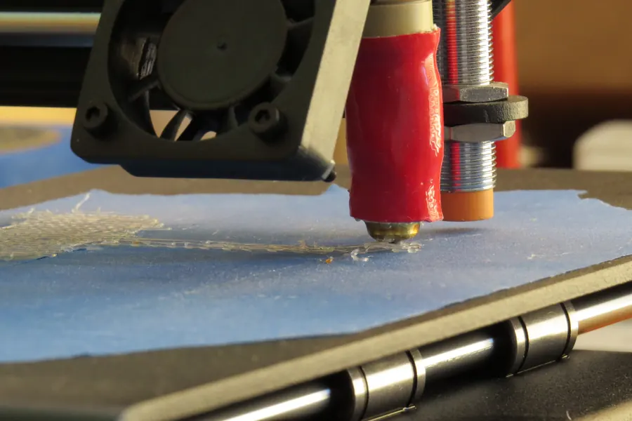
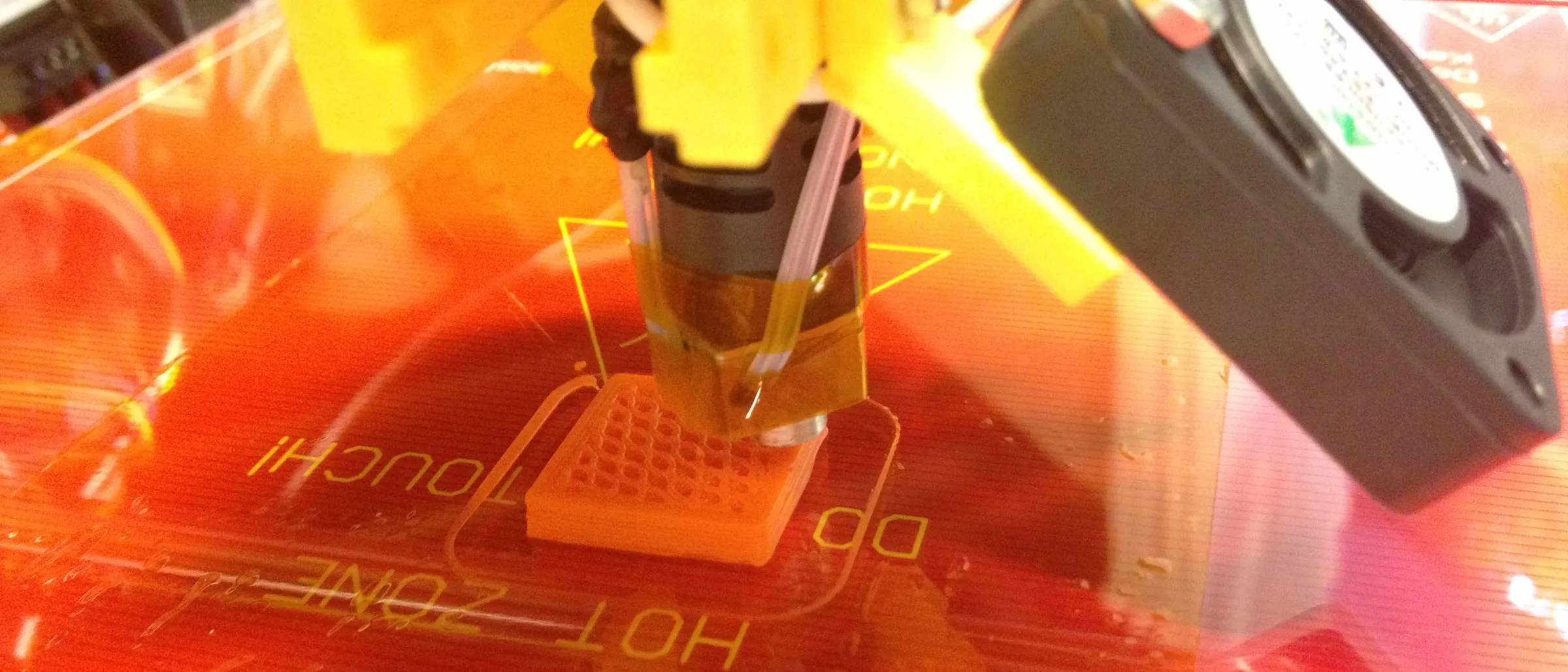
Prusa's MINI calibration guide illustrates three results. With the nozzle too high, neighbouring lines leave gaps. Too close, the lines are flattened excessively and ridges appear between them. The target is a connected patch without those ridges. Use that comparison as a visual starting point, then follow the calibration procedure for your own machine.
Keep the test patch after removing it from the plate. Note which face touched the bed and which edge faced the front of the printer. A photograph of the upper surface and a photograph of the underside preserve different information. Label them rather than relying on memory when you compare the next attempt.
| What the test shows | What to investigate first | What to record |
|---|---|---|
| Gaps between otherwise regular lines | Nozzle-to-bed distance using the machine's calibration procedure | Plate, profile and current offset, if adjustable |
| Ridges between heavily flattened lines | Whether the nozzle is too close | Photograph of the patch before removal |
| A problem confined to one part of the bed | Whether the same location fails on a repeat test | Position and orientation of each patch |
| Missing extrusion continuing above the first layer | Filament delivery and the extrusion troubleshooting procedure | Whether the defect appears on later layers too |
Identify how this printer measures the first layer
Prusa's Live Adjust Z instructions distinguish manually adjusted machines from load-cell-equipped models that calibrate the first layer automatically. An instruction to turn a Live Z control therefore needs a model attached to it. Do not assume a menu item from a MINI or an older i3 exists on a different printer.
Before testing, write down the printer model, firmware version, nozzle and selected plate profile. Open its current first-layer instructions and identify which steps are automatic. If the process reports an error, resolve that message before trying to compensate through the slicer. Stop a test if the nozzle scrapes the surface; do not continue lowering it to chase a better-looking line.
A copied offset has little diagnostic value without the machine and sheet it belongs to. Keep your own initial value in the test notes so that an unsuccessful change can be reversed. Use the adjustment method and increments specified by the manufacturer rather than importing someone else's number.
Separate the surface from the height test
Choose the cleaning and release instructions for the actual plate. Our smooth versus textured PEI guide compares the manufacturer guidance by surface and filament. A cleaning instruction for one coating should not be applied to another simply because both plates look metallic.
For a comparison, keep the plate, material and slicer profile unchanged. Clean the surface according to its instructions, let it reach the normal test condition, then repeat the same file. Record cleaning as the change for that attempt. If the result improves, you have an observation you can reproduce without having altered height, flow and temperature together.
Adhesion and later corner lifting deserve separate notes. A patch that never stays in place gives a different starting point from a broad part whose corners lift after several layers. For the second case, continue with the warping guide and keep the first-layer photograph as part of the record.
Use a small test and change one setting
Use the manufacturer's calibration pattern where one is supplied. Keep the exported file with the notes, rather than slicing a slightly different object each time. Give each run a short name, such as A for the starting point and B for the first adjustment. Record the exact change beside the result.
Choose what would count as an improvement before running B. For a height test, that might be closed gaps without new ridges. For a repeatability check, it might be the same patch printing consistently in the same position. This keeps the decision tied to the problem you observed.
If B is worse, return to A before trying a different explanation. Preserve the failed photograph too. A collection of labelled tests is useful when asking support for help; a list of every setting changed during an afternoon makes the sequence much harder to reconstruct.
Keep flow calibration as a separate job
Prusa's extrusion multiplier guide treats extrusion quantity as its own calibration task. It describes adjusting how much material is extruded, with a dedicated test and a material-specific result. That is a different control from the distance between nozzle and plate.
Finish the appropriate first-layer procedure before starting a flow test. Save a copy of the working profile, name the material being tested and follow the extrusion guide separately. If the same missing lines appear beyond the first layer, document that before changing the multiplier. Our nozzle-clog troubleshooting guide covers the filament-path investigation.
What to send with a support request
Include the printer model, firmware, nozzle, filament label, plate type and slicer profile. Attach the original test file and the labelled photographs. Say whether the defect repeats in the same bed position and whether it continues into later layers. Add the exact calibration step that failed, including any message shown on the printer.
Keep the last usable profile and the unmodified test file together. Those two files provide a clear starting point when you return to the printer or compare the result after maintenance.
Frequently asked questions
Should every printer use Live Adjust Z?
No. Check the model-specific instructions. Prusa distinguishes manually adjusted models from machines with load-cell-based automatic first-layer calibration.
What should I record before adjusting the first layer?
Keep the printer model, firmware, nozzle, plate, material and profile, plus photographs and the original test file.
Should I change flow and Z offset together?
Use separate tests. Otherwise a better or worse result cannot be attributed to one adjustment.